From manual modeling to automated LGSF design
Overview
A light-gauge steel framing company was designing everything in 2D, in local tools of the AutoCAD kind. A panel was a set of lines, so editing one meant redrawing it and pushing a change through a building was effectively impossible, while fabrication needed an LOD 500 model. Quantities lived in a separate spreadsheet and were recounted by hand. At some point it had stopped being engineering and turned into drafting.
We studied how their engineers design panels, wrote those conventions down with them as explicit rules, and built a set of Tekla Structures plugins on top of that rulebook: parametric wall, floor, and truss panels, wall generation from axis lines, and automatic specifications calculated inside the model.
The company moved from 2D drafting to an LOD 500 model that builds itself from their own rules. Engineers stopped drawing panels and started managing the design: quantities always current, drawings always in sync, and a change propagates through the project instead of restarting it.
Background
The company designs and fabricates light-gauge steel framing. Before working with us there was no BIM model in the process at all: panels were drawn in local 2D tools of the AutoCAD kind, the way the shop had always worked. That holds up only while nothing changes: a panel is linework, so editing one means redrawing it, and there is nothing that carries a revision through the rest of the building. Meanwhile fabrication and their clients were asking for LOD 500: every stud, track, screw, and accessory modeled exactly as it will be made.
Problem
2D linework can't carry an LOD 500 panel
Simply moving to Tekla Structures would not have solved it either. An LGSF panel is dozens of thin-gauge members with strict rules for spacing, openings, and connections; modeling that by hand is accurate but so slow that it consumes the whole schedule, and the next design change starts the same work over. Quantities had the same problem: insulation, screws, and accessories were counted by hand in a separate spreadsheet, so they went stale the moment the geometry moved.
Panels existed as 2D linework, so editing one meant redrawing it.
LOD 500 was a fabrication requirement, not a nice-to-have.
Hand-modeling the same panels in Tekla was accurate but far too slow to be viable.
Fastener, insulation, and accessory counts were maintained manually, outside the design.
Analysis
Before writing any code we went through their design process with them: how a wall panel is composed, where studs land around openings, which accessories belong to which connection, how floor and truss panels differ, and what the fabrication line expects at the other end. Together we wrote those conventions down as explicit rules. Until then they lived as tribal knowledge in a few heads. That rulebook became the specification for the plugins.
How it works
We took Tekla Structures as the platform and built a set of plugins on top of it: one for each panel type, plus generators and quantity tools, all with the agreed rules built in:
Parametric panel plugins – wall, floor, and truss
A plugin per panel type, with the construction rules embedded. Geometry is generated from parameters at LOD 500 (studs, tracks, connections, and accessories included) instead of being placed member by member.
Wall generation from axis lines
Draw the line and get the panels: the generator lays out the wall run along the building axes, splits it into panels by the agreed rules, and models each one in full.
Automatic specifications from the model
Fasteners, insulation volume, and accessories are counted from the model itself. Nobody has to work out how many screws a panel takes: the quantities follow the geometry and update with it, with no separate spreadsheet.
One connected toolset
The plugins share the same rules and the same data, so walls, floors, and trusses stay consistent with one another. Change a parameter and the model – and its quantities – follow.
Result
Design is no longer the bottleneck. The company went from redrawing panels in 2D to managing a model that builds itself from their own rules.
Panels are generated at LOD 500: every member, connection, and accessory modeled as it will be fabricated.
Wall runs come from axis lines instead of being assembled panel by panel.
Fastener, insulation, and accessory quantities are read from the model, not from a spreadsheet.
A design change is a parameter change, so it propagates through the project instead of restarting it.
-70%
Modeling time per project
2
Hours on documentation
LOD 500
Fabrication-ready model detail
Technologies
Tekla Open API
C#
.NET
Other Cases
From internal plugin to protected product
How we helped an LSTK company scale its engineering capacity by turning an internal Tekla Structures plugin into a license-managed product external contractors can use
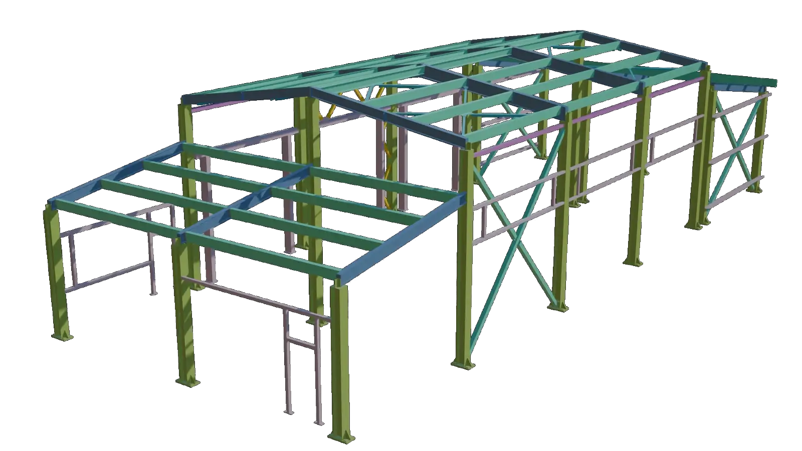
From manual modeling to data-driven steel frame design
How we replaced a 3-5 day manual BIM workflow with automated model generation from structural analysis data - cutting modeling time by over 90% and eliminating discrepancies between analysis and design
Find out where you're losing time and money right now